

1 Project Objectives and Scope
1.1 Project Objectives
This project establishes a VPN connection between Oneasy Cloud Management and the on-site OLT management network, enabling remote access to OLTs and centralized management from the cloud.
This document defines OLT access methods, network topology, management addressing and VLAN planning, VPN setup, and device onboarding procedures. It provides a reference for on-site implementation and ongoing operations. The network design also reserves the connectivity required for future ONU TR-069 management.
1.2 Supported Devices
Oneasy supports management of the following OLT brands and product series:
| Index | Vendor | OLT Type | Notes |
|---|---|---|---|
| 1 | Huawei | MA5800-X7 | |
| 2 | Huawei | MA5800-X17 | |
| 3 | Huawei | MA5800-X15 | |
| 4 | Huawei | MA5680T | |
| 5 | ZTE | C600 | |
| 6 | ZTE | C300 | |
| 7 | ZTE | C320 | |
| 8 | Fiberhome | AN6001-GF16 | Planned to be released soon(2026.12) |
| 9 | Fiberhome | AN6001-G16 | Planned to be released soon(2026.12) |
| 10 | Fiberhome | AN6000-7 | |
| 11 | Fiberhome | AN6000-2 | |
| 12 | Fiberhome | AN6000-17 | |
| 13 | Fiberhome | AN6000-15 | |
| 14 | Fiberhome | AN5516-04 | |
| 15 | CDATA | FD1602S-C2 | Planned to be released soon(2026.10) |
The table above describes the platform's supported device range. For this project, the actual device models, software versions, quantities, sites, and management addresses are defined in the project device inventory. Available management functions depend on support for the specific model and software version.
1.3 Implementation Scope
This document covers the following implementation tasks:
1. Select in-band or out-of-band OLT management access and define the on-site device connections.
2. Plan and configure OLT management addresses, management VLANs, gateways, and associated routes.
3. Configure connectivity between MikroTik and the OLT management network.
4. Confirm that the on-site Internet uplink meets the requirements for establishing a Oneasy VPN.
5. Create a Oneasy VPN, configure the on-site connection, and check tunnel status.
6. Verify connectivity to the OLT management address and the required management services.
7. Add the OLT to Oneasy Cloud Management and check device connectivity.
This document uses a Huawei MA5800-X7 OLT and a MikroTik router as the implementation example. Other brands and models can follow the same access procedure, using the configuration commands, interface names, and management parameters appropriate to each device.
1.4 Implementation Boundaries
On-site implementation involves Oneasy Cloud Management, the VPN, MikroTik, the OLT, and any switches and Internet edge routers in the actual connection path.
If an intermediate switch is used, allow the relevant VLANs according to the design. The Internet uplink must allow MikroTik to reach the services required to establish the VPN. Responsibilities for configuring and maintaining the relevant devices must be agreed before implementation.
This deployment reserves network connectivity for future ONU TR-069 management. The dedicated VLANs, addresses, routes, ACS services, and terminal parameters required for ONU TR-069 will be defined separately when that management function is implemented. Completing OLT onboarding does not constitute delivery of ONU TR-069 management.
2 Selecting the Access Method
2.1 Preferred Method
In-band OLT management access is the preferred method for this project. The OLT uplink port carries the management VLAN through the on-site network to MikroTik, which connects to Oneasy Cloud Management through the VPN.
In-band access uses VLANs to separate the management network, facilitating consistent planning of OLT management connectivity. It also provides a basis for the VLAN transport and network connectivity required for future ONU TR-069 management.
2.2 In Band Access
A typical in-band connection path is: OLT uplink port > switch > MikroTik > Internet edge router > Internet and VPN > Oneasy Cloud Management. The OLT can also connect directly to MikroTik where site conditions permit.
In the example design used in this document:
1. The OLT uplink port carries the management VLAN, and the management address is configured on the corresponding VLANIF interface.
2. The intermediate switch transparently forwards the management VLAN at Layer 2.
3. MikroTik terminates the management VLAN and serves as the gateway for the OLT management network.
4. MikroTik establishes the Oneasy VPN through the on-site Internet uplink.
5. The relevant routes are configured to provide bidirectional reachability between Oneasy Cloud Management and the OLT management address.
This document uses VLAN 200, OLT management address 192.168.200.2/24, and MikroTik gateway address 192.168.200.1/24 as configuration examples. Adjust these values to match the site's addressing and VLAN plan for production deployment.
2.3 Alternative Method
Out-of-band access can be used when the OLT uplink cannot carry the management VLAN, or when the existing network explicitly requires a separate management interface. In this method, the OLT out-of-band management port connects to MikroTik.
The out-of-band design uses the dedicated OLT management interface to establish the management network, which connects to Oneasy Cloud Management through MikroTik and the VPN. Confirm that the out-of-band interface on the specific model supports the required management services and routing configuration.
After onboarding the OLT through out-of-band access, any subsequent ONU TR-069 management still requires separate planning of the relevant VLANs and network paths.
2.4 Selection Criteria
Use in-band access whenever site conditions permit. If out-of-band access is selected, record the reason and the arrangements for future expansion.
Before production deployment, specify the selected access method, device interfaces, management VLAN, management addresses, gateway, and VPN routes in the project topology and parameter table. These records form the basis for subsequent configuration and acceptance.
3 Network Topology and Configuration Prerequisites
Version prerequisite: The Oneasy automatic configuration script is intended for RouterOS 7 releases later than 7.0. The original support description states "V7.0 or later". Record the actual RouterOS version before running the script.
Using a Huawei MA5800-X7 OLT and a MikroTik router as an example, this document explains how to prepare the OLT management network, establish the Oneasy VPN, and add the OLT to Oneasy Cloud Management. Before configuring the devices, confirm the connections and VLAN connectivity shown below.
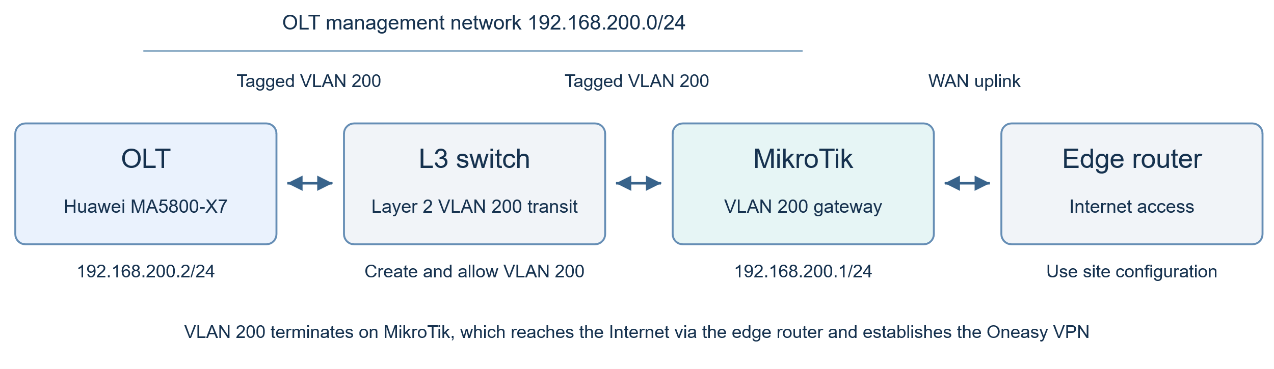
Figure 3-1 In-band management network topology
The OLT connects to an L3 switch. Another switch port connects to MikroTik, whose WAN port connects to the Internet edge router. In this example, the L3 switch only forwards VLAN 200 at Layer 2. The OLT uplink port, the relevant switch ports, and the connected MikroTik port must all allow tagged VLAN 200 traffic.
The management gateway resides on MikroTik. VLAN 200 terminates on MikroTik, which accesses the Internet through the edge router and establishes the Oneasy VPN.
4 Connecting the OLT Uplink to MikroTik for In Band Management
4.1 Parameter Planning
The parameters used in this example are as follows:
OLT: The VLANIF 200 interface uses 192.168.200.2/24.
L3 switch: Configure the relevant ports in trunk mode and allow VLAN 200. Switch configuration is outside the scope of this document. Whether a switch is required depends on the actual topology; the OLT can also connect directly to MikroTik.
MikroTik: The VLAN 200 interface uses 192.168.200.1/24.
Before configuration, ensure that MikroTik can access the Internet through the edge router. Configure the OLT SNMP version and read and write community strings, and prepare the Telnet username and password.
4.2 OLT Configuration
4.2.1 Huawei OLT In Band Management Access
4.2.2 ZTE C300 and C600 In Band Management Access
4.2.3 FiberHome AN6000V7 In Band Management Access
FiberHome AN6000V7 in-band access
4.2.4 C DATA FD1602S C2 In Band Management Access
4.2.5 VSOL V1600G1 Access Configuration
5 MikroTik Configuration
This example uses OLT uplink port 2 and MikroTik ether2, connected through an L3 switch.
OLT uplink port 2 connects to the L3 switch. Another switch port connects to MikroTik ether2.
Both switch ports must allow tagged VLAN 200 traffic. The following commands assume that the bridge is named bridge and ether2 is already a member of that bridge. Use the actual bridge name configured on the device.
5.1 Configure the Tagged Port
/interface/bridge/port/set [find where interface=ether2] \
ingress-filtering=yes frame-types=admit-only-vlan-tagged
5.2 Configure the Bridge VLAN Table
/interface/bridge/vlan
add bridge=bridge vlan-ids=200 tagged=bridge,ether2
5.3 Create a Layer 3 VLAN Interface on the Bridge
/interface/vlan
add name=vlan200 interface=bridge vlan-id=200
5.4 Configure the Layer 3 IP Address
/ip/address
add address=192.168.200.1/24 interface=vlan200
5.5 Enable VLAN Filtering
Before enabling VLAN filtering, confirm that all existing service VLANs and the current management path are correctly allowed in the Bridge VLAN table. The following command affects the entire bridge. Run it only when local or alternative management access is available.
/interface/bridge/set [find where name="bridge"] vlan-filtering=yes
5.6 Test Connectivity
5.6.1 Ping Connectivity Test
/tool/ping 192.168.200.2 src-address=192.168.200.1 count=20
Pass criteria: Responses are received from the OLT management address. Record the number of packets sent and received, and any packet loss. If persistent packet loss occurs, troubleshoot the connection before proceeding.
5.6.2 SNMP Connectivity Test
/tool/snmp-get address=192.168.200.2 port=161 community=public12 oid=1.3.6.1.2.1.1.1.0 version=2c
Note: 192.168.200.2 and public12 are example values. Replace them with the actual management address and community string.
Pass criteria: Using the actual SNMP version and community string, the query returns valid information such as the device system description. This query verifies read access only; it does not verify write permissions.
5.6.3 Telnet Connectivity Test
/system telnet address=192.168.200.2 port=23
Pass criteria: The OLT Telnet service can be reached and login succeeds using the prepared username and password. Successful port connectivity alone does not validate the account credentials.
If Ping, Telnet login, and SNMP queries from MikroTik to the OLT all pass, the on-site management path and the corresponding services are available, and VPN creation can proceed. If any test fails, check addressing, interfaces, VLANs, routes, and service configuration.
6 Creating the VPN Tunnel
6.1 Check the Computer Date and Time
Confirm that the computer's date, time, and time zone are correct. Enable Set time automatically, then click Sync now. An incorrect computer time may prevent login to Oneasy Cloud Management.
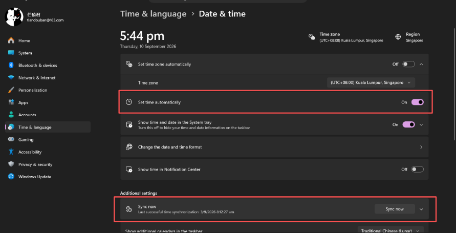
Figure 6-1 Computer date and time settings
Configure time synchronization as shown above. Set the time zone according to the computer's location.
6.2 Sign In to Oneasy Cloud Management
Open Settings > VPN Mgmt.
Click New Tunnel.
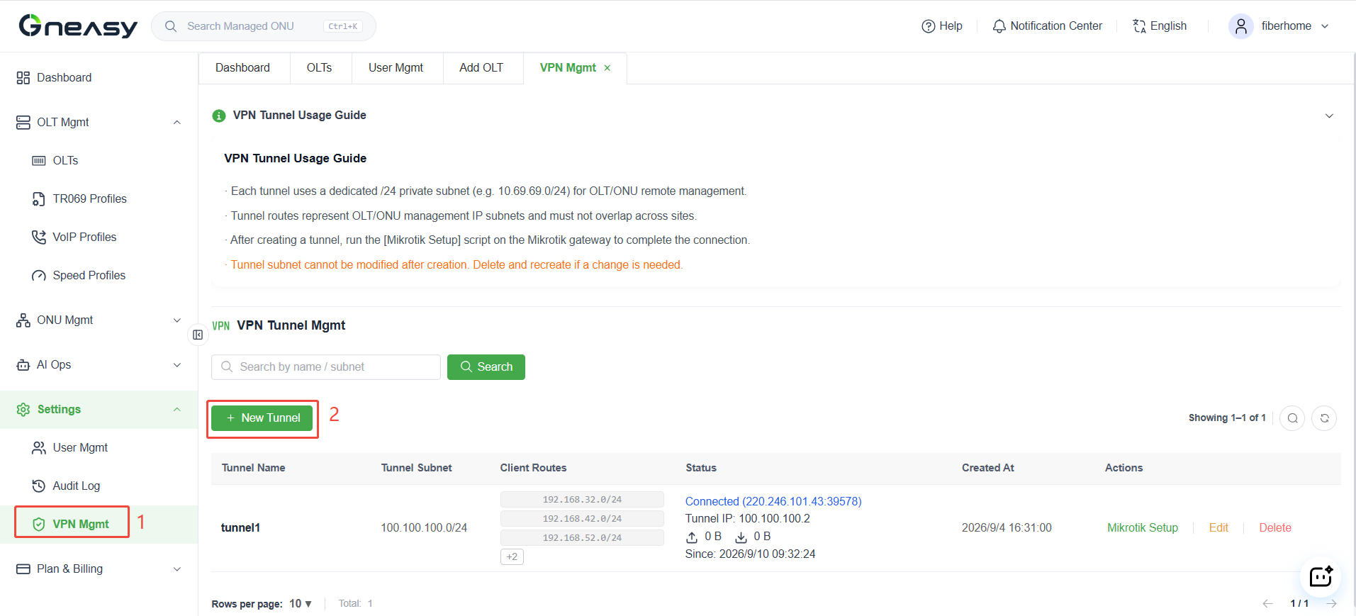
Figure 6-2 Entry point for creating a VPN tunnel
6.3 Configure Client Routes and Create the Tunnel
In Client Routes, enter 192.168.200.0/24, the subnet containing the OLT management IP address. Leave the other parameters at their default values, then click Create Tunnel. Tunnel names shown in the following screenshots are examples; use the name of the tunnel you actually create.
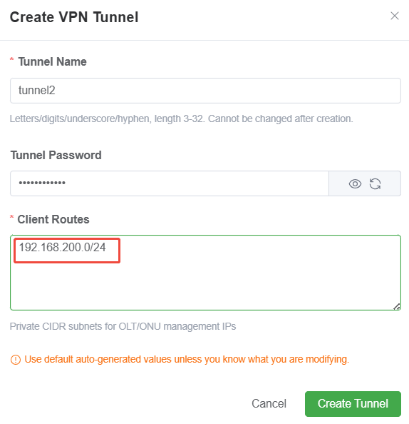
Figure 6-3 Example client route parameters
6.4 Open the MikroTik Setup Page
In the row for the tunnel you created, click Mikrotik Setup.
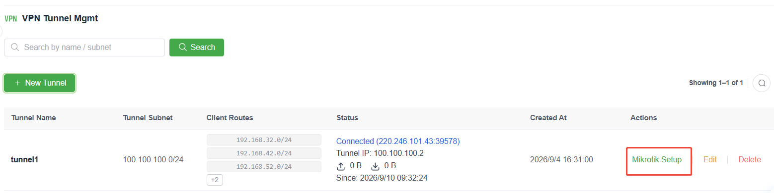
Figure 6-4 Entry point for MikroTik setup
6.5 Copy the Tunnel Configuration Command
Click Copy to copy the command.
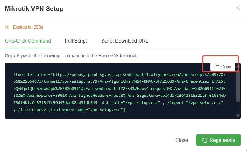
Figure 6-5 Copying the tunnel configuration command
6.6 Run the Command and Check Tunnel Status
In MikroTik WinBox, open New Terminal, paste the copied command, and run it. Execute the command within the validity period displayed on the page, which is 5 minutes in this example. If it has expired, regenerate the command, then copy and run it again.
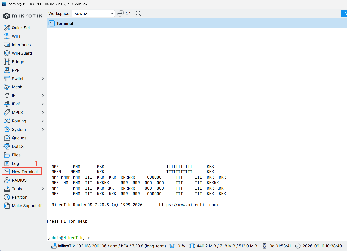
Figure 6-6 Opening the MikroTik terminal
Before running the command, ensure that MikroTik can access the Internet.
After the script runs successfully, the terminal displays: Script file loaded and executed successfully.
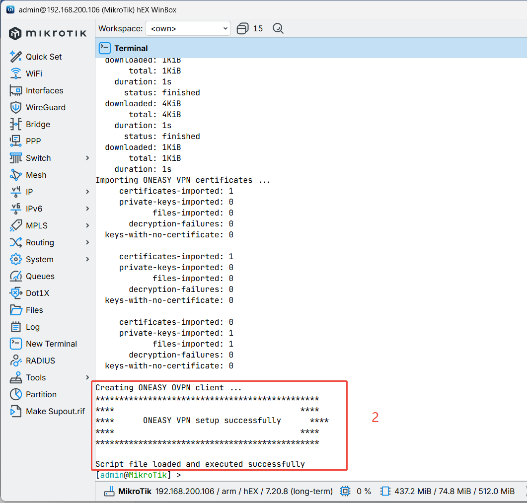
Figure 6-7 Example of successful script execution
After the script runs successfully, open Interfaces in WinBox and locate the corresponding VPN tunnel interface. An R flag before the interface indicates that it is running.
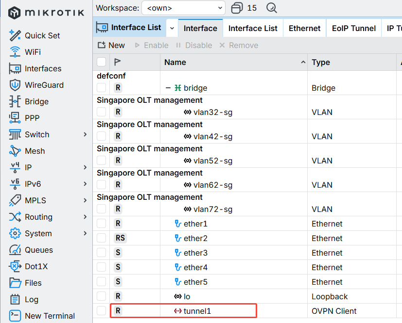
Figure 6-8 VPN interface running status
You can also open IP > Addresses in WinBox to view the IP address assigned to the tunnel interface. This example uses 100.100.100.X/24; use the address actually assigned to your tunnel.
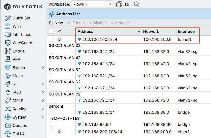
Figure 6-9 Example tunnel interface address
After the tunnel interface is running and has an IP address, also verify Ping, Telnet, and SNMP connectivity to the OLT from the Oneasy cloud server. Proceed to Chapter 7 to add the OLT only after all three tests pass. Interface status alone is not sufficient to establish end-to-end connectivity.
7 Adding the OLT to Oneasy Cloud Management
7.1 Confirm the Prerequisites
Confirm that the computer time check in Section 6.1 has been completed and that connectivity tests from the cloud server to the OLT have passed. Prepare the device model, management address, Telnet credentials, and SNMP parameters.
7.2 Open the Add OLT Page
Sign in to Oneasy Cloud Management, open OLT Mgmt > OLTs, and click Add OLT.
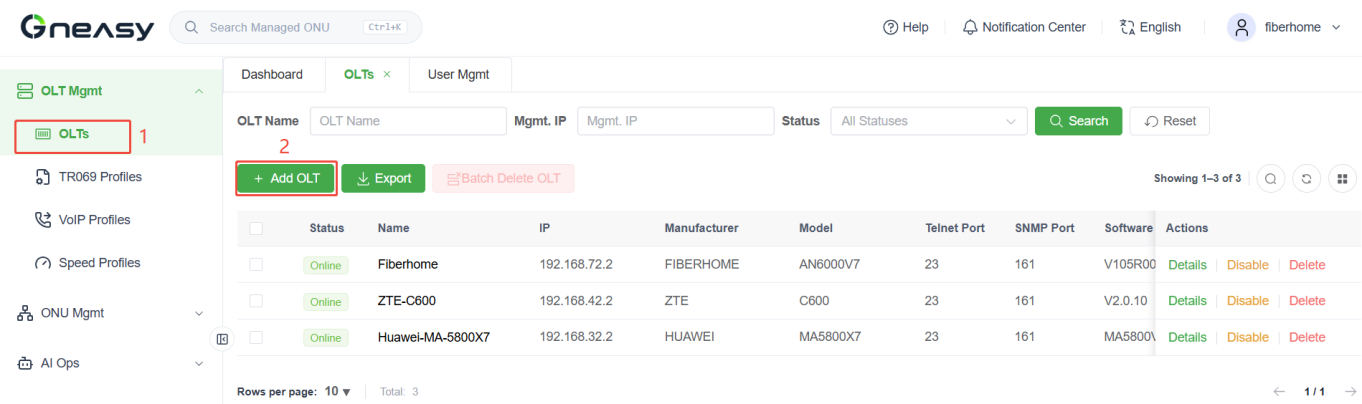
Figure 7-1 Entry point for adding an OLT
7.3 Enter the OLT Connection Parameters
Enter the OLT basic information, Telnet login credentials, and SNMP parameters.
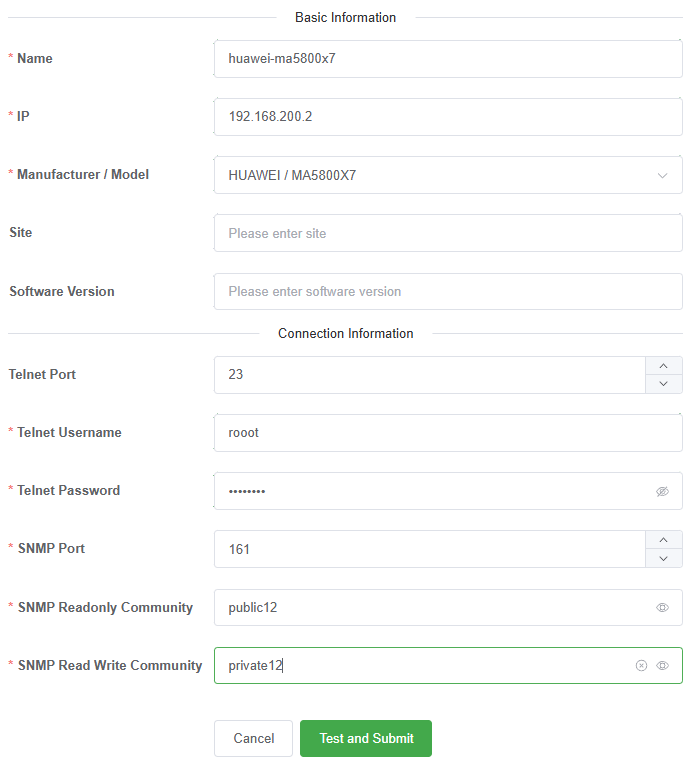
Figure 7-2 Example OLT connection parameters
Enter the actual device parameters; the screenshot is for reference only. The Telnet username and password must match an account configured on the OLT. If you use the huawei account created in the Huawei configuration document embedded in Section 4.2, enter huawei as the username. The SNMP community strings must also match the device configuration.
7.4 Test and Submit
After completing the fields, click Test and Submit. Once submission succeeds, the device appears in the OLT list.
After adding the OLT successfully, retrieve its model, software version, or other configuration information and compare it with the actual device information. If configuration deployment must be verified, select a test item confirmed to have no impact on live services. Check that it takes effect, then revert the test changes.
After completing on-site connectivity tests, cloud connectivity tests, OLT onboarding, and information retrieval or configuration deployment tests, record the results and save the OLT configuration as required for the specific model.
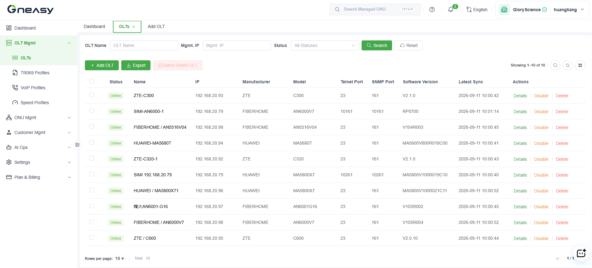
Figure 7-3 Example OLT list
8 Connecting the OLT Out of Band Management Port to MikroTik
8.1 Huawei OLT Out of Band Management Access
8.2 ZTE OLT Out of Band Management Access
8.3 VSOL V1600G1 Out of Band Management Access
See the VSOL configuration document embedded in Section 4.2.5. Select the out-of-band access method and the corresponding MikroTik configuration.
8.4 FiberHome AN6000V7 Out of Band Management Access
FiberHome AN6000V7 out-of-band access
The C-DATA FD1602S-C2 covered in this document has no out-of-band management port and supports in-band access only.